Heated Chamber Upgrade to 3D Printer Product
Desktop Metal Fall 2020
Problem Statement:
In order to create more accurate parts on the Studio system printer, the print area needed to reach and maintain a certain elevated temperature
Inital Testing:
I created a cage of thermocouples that were connected to a DAQ system in order to collect initial temperature data
-
The cage covered all the corners of the print area and moved with the bed during a simulated print
My team found that the chamber of the Studio system printer was not heating up evenly:
-
The lower part of the chamber below the dump buckets would heat up very quickly and stay hot
-
The upper part of the chamber would not reach the required temperature even after a 3 hour long simulated print
Decided to design a solution to circulate air around the chamber.
Design Iterations:
1
Replace the heater units with a different type from another version of the Studio printer
This didn’t change the difference in heat, the bottom part of the print area still got a lot hotter
2
I designed a deflector that could be attached to the heat vents to direct the airflow around the dump buckets (shown in diagram)
Any direction the deflector pointed got a lot hotter, but the heat never evened out throughout the chamber

Studio Printer with dump buckets marked.
Design iteration #2: Deflection insert designed in SolidWorks and 3D printed using an HP Nylon printer.
3
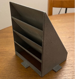
The final attempt was to change one of these dump buckets so that it had air vent holes and a draft angle so that it would direct flow into the center of the chamber, above the print area
After extensive thermal analysis with the thermocouples, this solution proved to allow enough circulation in the chamber order to meet the desired temperature range
Next Steps:
I worked testing on all available Studio printers in the company to check for any differences that could affect the solution, results were presented internally
After approval, I drafted manufacturing drawings, top level assemblies and designed packaging to ship the solution to customers

Design iteration #3: Redesigned dump bucket with draft angle and holes to allow for air to flow throughout the chamber. 3D printed using an HP Nylon printer.
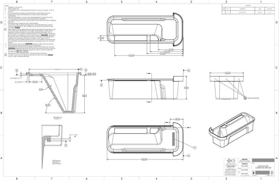


All the SolidWorks drawings I worked on for the heated chamber project. Click to enlarge images.